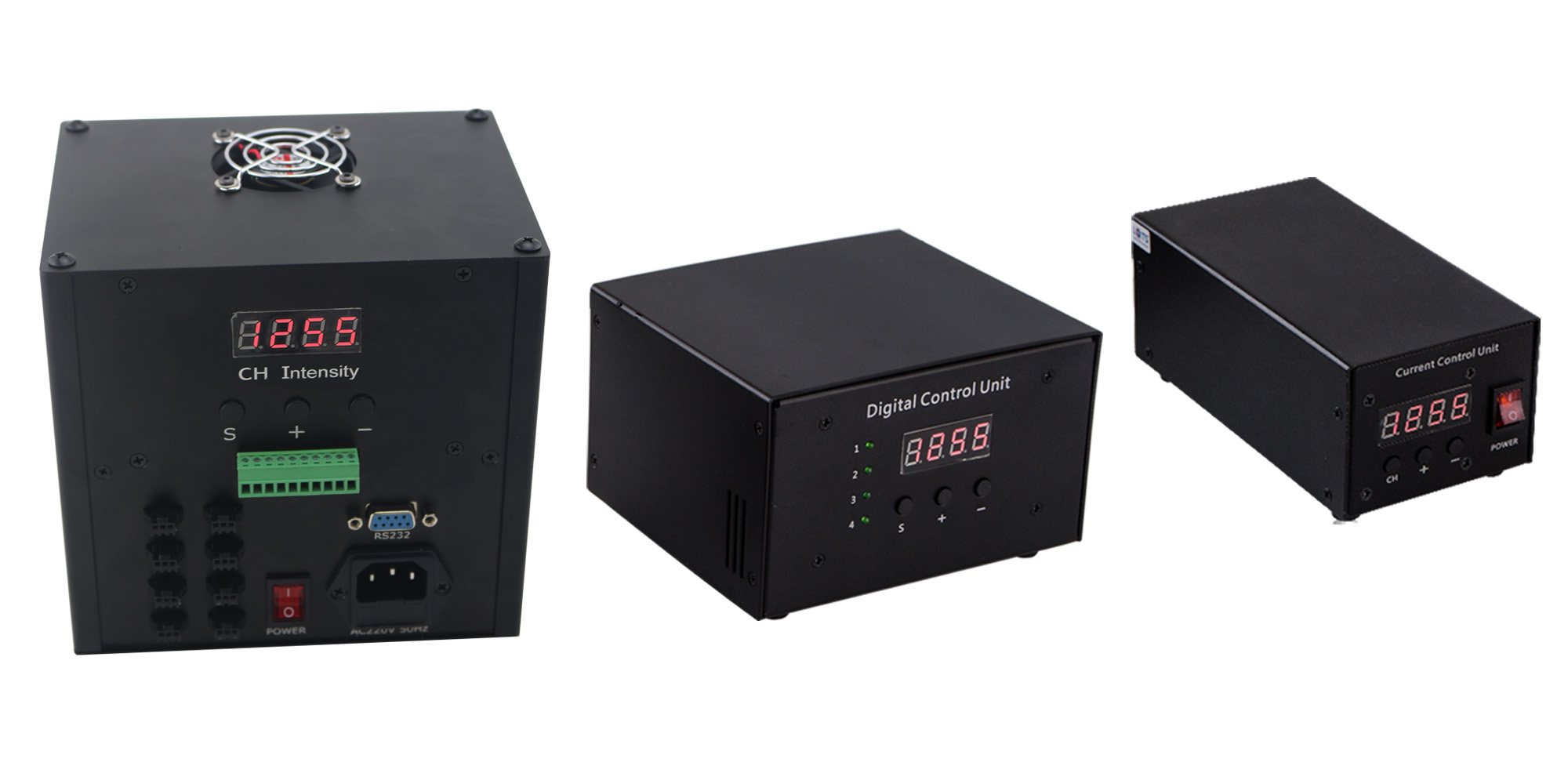
KMN-DPC
The digital controller can supply high accuracy 256 degrees of intensity adjustment for LED lights, which is easy to operate and has high output accuracy. The controller not only can be invoked as normal power controller but also as strobe controller. It can be controlled by push-on button, RS232, USB, RJ45 (remote control) etc. The strobe controller can achieve by signal communication and external trigger. As the preferred choice of the light power source, the digital controller is perfect for the light with high control requirement.
The Features of the Digital Controller
1.Having 256 degrees high precision change to control the intensity, the controller is easy to operate by using push-on button or PC while every single channel is individually adjustable;
2.The digital showing screen shows the range of the intensity and can operate through push-on button;
3.The digital controller can use communication methods like RS232, RJ45, USB etc. and eight controllers can be operated at the same time when using RJ45 to communicate;
4.Can observe whether the corresponding channels are turned on or not through the corresponding LED;
5.The high speed opt coupler is adopted and the trigger level can be selected to get fast response and high reliability;
6.Having a function of memory that can show the previous shutdown content automatically after restarting.
Parameters of the Digital Controller
| Model | KMN-DPC24##-#S | KMN-DPC24120-8 | Remarks |
| Communication modes | RS232 | RS232,USB,RJ45 | Eight controllers can be operated through a PC |
| Intensity adjustment mode | PWM adjustment | Adjusting voltage by changing the duty cycle of PWM |
| Trigger delay time | <40us | Load related |
| External trigger frequency | <1/T | Decide by trigger cycle, e.g.: T=1ms,then external trigger, the maximum frequency is up to 1K |
| External trigger input voltage | High level 5-24V, low level 0-1.5V | Positive or negative trigger is optional |
| NO. of channels | Channel 2、4 | Channel 8 |
|
| Intensity adjustment level | 256 level regulation |
|
| Driving mode | Constant voltage, Change the duty cycle |
|
| Input voltage | 170-260V |
|
| Standby power | <3W |
|
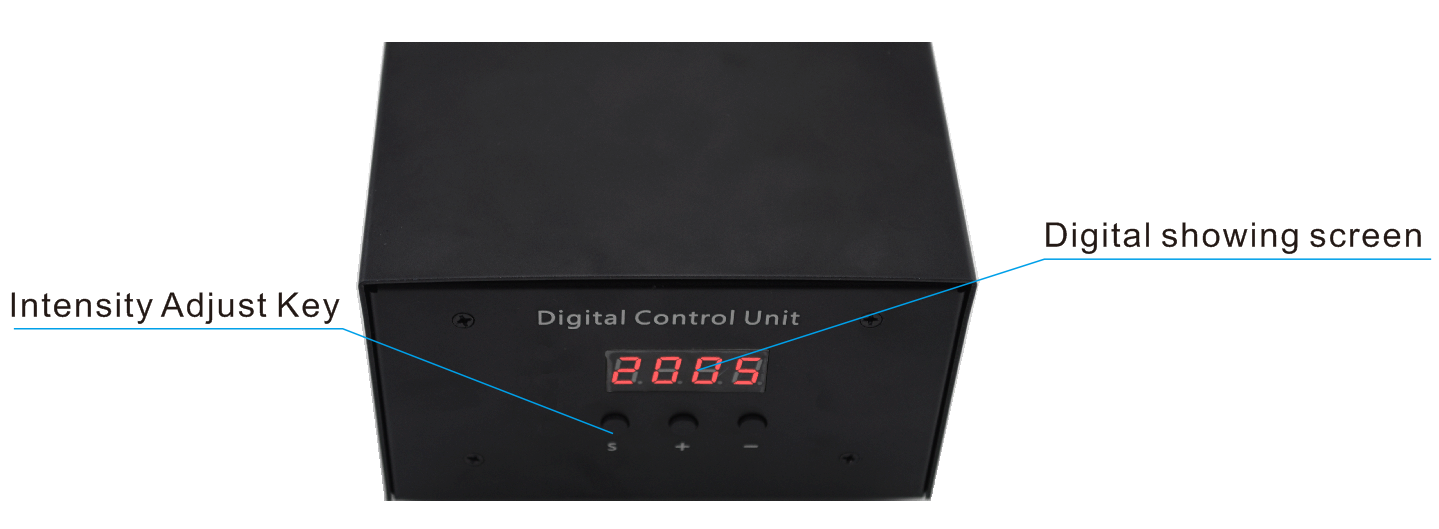
(1)The Function of Intensity Adjust Key
The first button from left (S) is selection key, by which you can press to switch channel and then 4 channels can be set up;
The second button from left (+) is series plus, the intensity increases one level and the digital tube plus 1 with every press;
The third button from left (-) is series minus, the intensity decreases one level and the digital tube minus 1 with every press.
(2)The Content of Digital Showing Screen
The first bit from left is channel display bit, display numbers would switch between “1、2、3、4、H” when press “S” key, “1” to “4” is the current set channel and “H” is the selection of trigger function.
When the channel value is between “1”-“4”, expressing in decimals, the after three bit as the parameter status bit and the value can be adjusted from 000~255.When the channel value is “H”, the selections are 1 and 0 only, (1 is the positive trigger and the output is open; 0 is the negative trigger and the output is off.)
For example: “1050” displayed on the digital showing screen means the first channel intensity level is 50 degrees.
When “H 1” is displayed, it means all output is open currently (at this time, if there is a high-level of access from the trigger, then the corresponding channel will be closed.)
(3)Special cases
When the channel value is “000”, then the corresponding channel has no voltage output.
While any channel’s parameter status bit value is in the range of 001~255, then the corresponding channel outputs normally.
After the power supply is switched on and the controller is turned on, the digital tube display output is saved as the last time data before the controller is closed. E.g.: When the controller is closed, it displays “3168”. The display output would be “3168” also when it restarts.
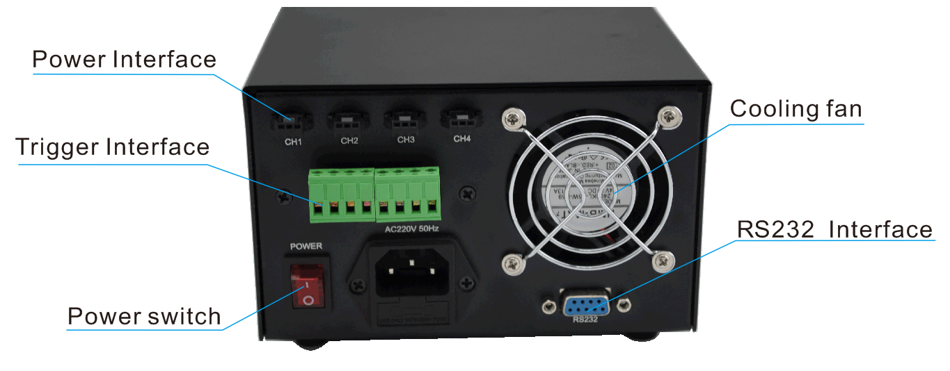
(1) Light Source Interface
As shown in the figure above, there are four channels output interface, “CH1”, “CH2”, “CH3”, and “CH4”. The maximum of output voltage is 24V adjustable and the light can be connected directly.
(2)Trigger Interface
The controller has a total of four channels trigger input corresponding to the four output channels individually. Connect the trigger signal to the “+” and “-” pole of the corresponding input when the external trigger is necessary to triggered.
(3) RS232 Interface
After connecting to PC with the null modem cable, RS232 can be used to communicate with the PC and through KONMANN’ digital control software or self-programming can achieve the adjustment of PC towards the light.
Wiring Method
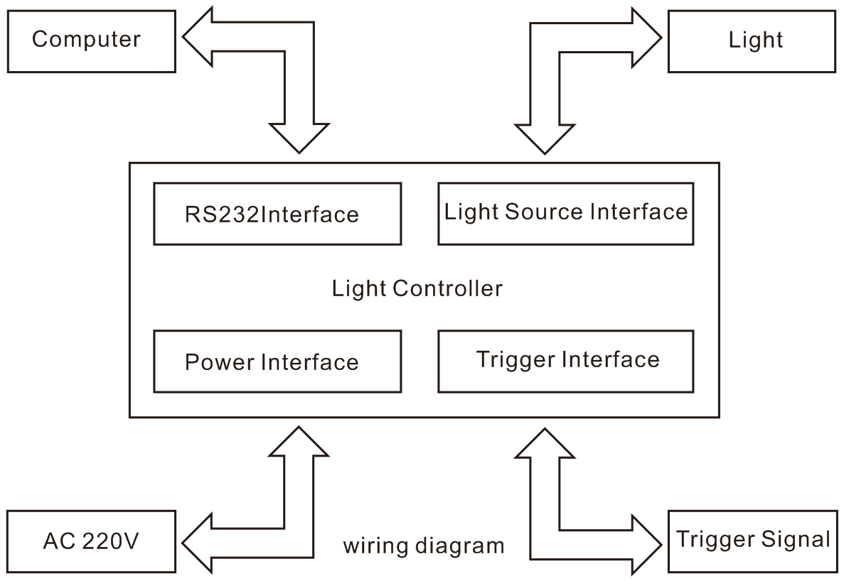
(1)Connect the light source with the controller. (Refer to the wiring diagram)
(2)If the external trigger control is needed, the external trigger signal source has to connect to the controller. (Refer to the wiring diagram)
(3)Access powers (220VAC), press the red switch button "-", "O" raised, the indicator light on, indicating that the power has been on.
(4)If you need to use the computer to control the intensity of the light, please use RS232 data cable to connect the PC with the controller in the shutdown state and then use the Demo program that provided by us or your company’s own self-program to conduct the control. While using the serial port to operate, the parameters of each channel can still be set manually, that is, the host computer and the controller can set the parameters, and do not need to carry out the mode conversion. Please refer to the following chapters for Demo program instructions.