KMN-STU
With internal and external trigger function, KONMANN strobing controller is a high performance light controller which output voltage is 48V, adjustable pulse width is 0-999us and sync output camera trigger signal is 12V. Its high and short-time break-over voltage can inhibit the LED internal temperature so as to increase the intensity and life span of the light.
The Features of the Strobing Controller
Adjustable pulse width(0-999us) and adjustable conducting time(cycle 1.42ms);
Pulse width adjusted by hand;
Brightness enhancement function: improve the output voltage, intensity increased by more than 200% for an instant, extend the life of the light;
External trigger: lighting on demand;
Internal trigger: lighting with a fixed frequency;
Data storage: every time you modify, the data will be saved automatically;
Short-circuit protection: the self-recovery function of short circuit in short time.
Parameter Description
| Item | Parameter | Remarks |
| Output voltage | 48V | Fixed |
| Adjustment mode | PWM adjustment | Adjustable pulse width(0-999us) |
| No. of channels | Two channels | Independently controlled |
| Trigger delay time | <20us | |
| External trigger signal | 5V-24V | Rising edge trigger, the trigger interval >1.42ms |
| Internal cycle | 1.42ms | |
| Working temperature | 0~60℃ | |
| Max single output power | 60W | The total output of the two channels is not over 60W |
| Power supply | 100~240VAC 1.5A | |
| Standby power | <3W |
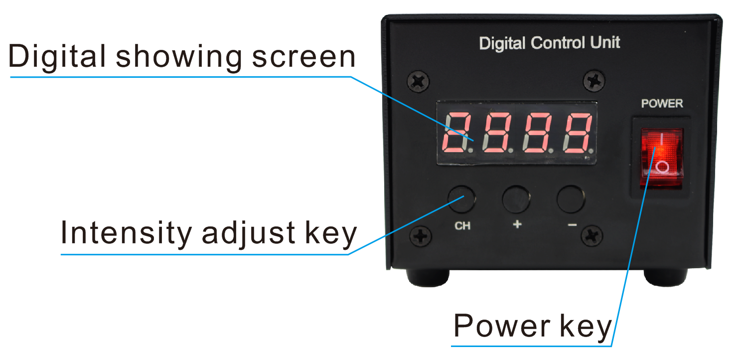
The Function of Intensity Adjust Key
The first key CH: showing 1 and 2 in turn by each press
The second key +: the pulse width increases 1us by each press (increasing rapidly by long press)
The third key -: the pulse width reduces1us by each press (decreasing rapidly by long press)
The Content of Digital Showing Screen
The first number on the digital showing screen is the No. of channels. The three number displayed in the back is pulse width.
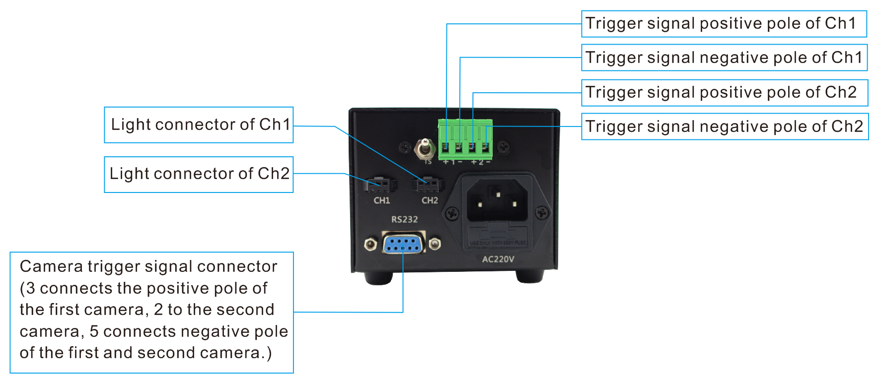
Controller Wiring Method
(1)Connecting the light with the light connector (refer to Operation Panel Instructions);
(2)If the external trigger is needed, please connect the external signal source with the trigger connector. “+”matches positive pole while“-”matches negative pole (refer to Operation Panel Instructions);
(3)Power source connect-in (AC 220V): pushing the red switch button “—”, “O” bulging with indicator light on, indicating power on.
Trigger Output Connector
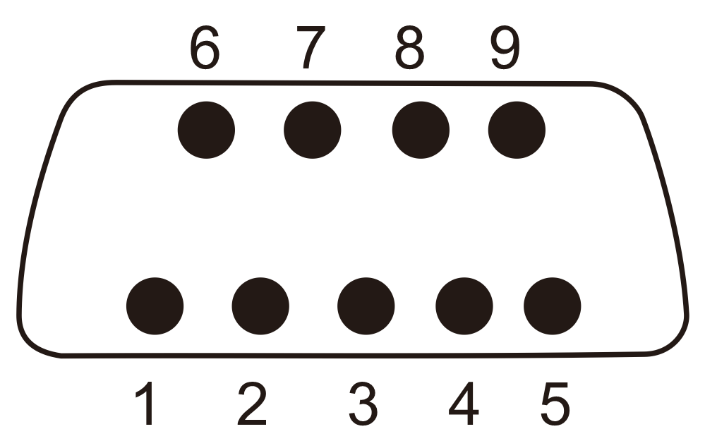
The trigger output connector uses DB9 connector (refer to Pin Diagram):
(1)3 and 5 are the trigger signal output of the first channel. 3 is positive pole while 5 is negative pole.
(2)2 and 5 are the trigger signal output of the second channel. 2 is positive pole while 5 is negative pole.
(3)The trigger signal output of the first and second channel shares one negative pole.
The Wiring Diagram of the Strobing Controller
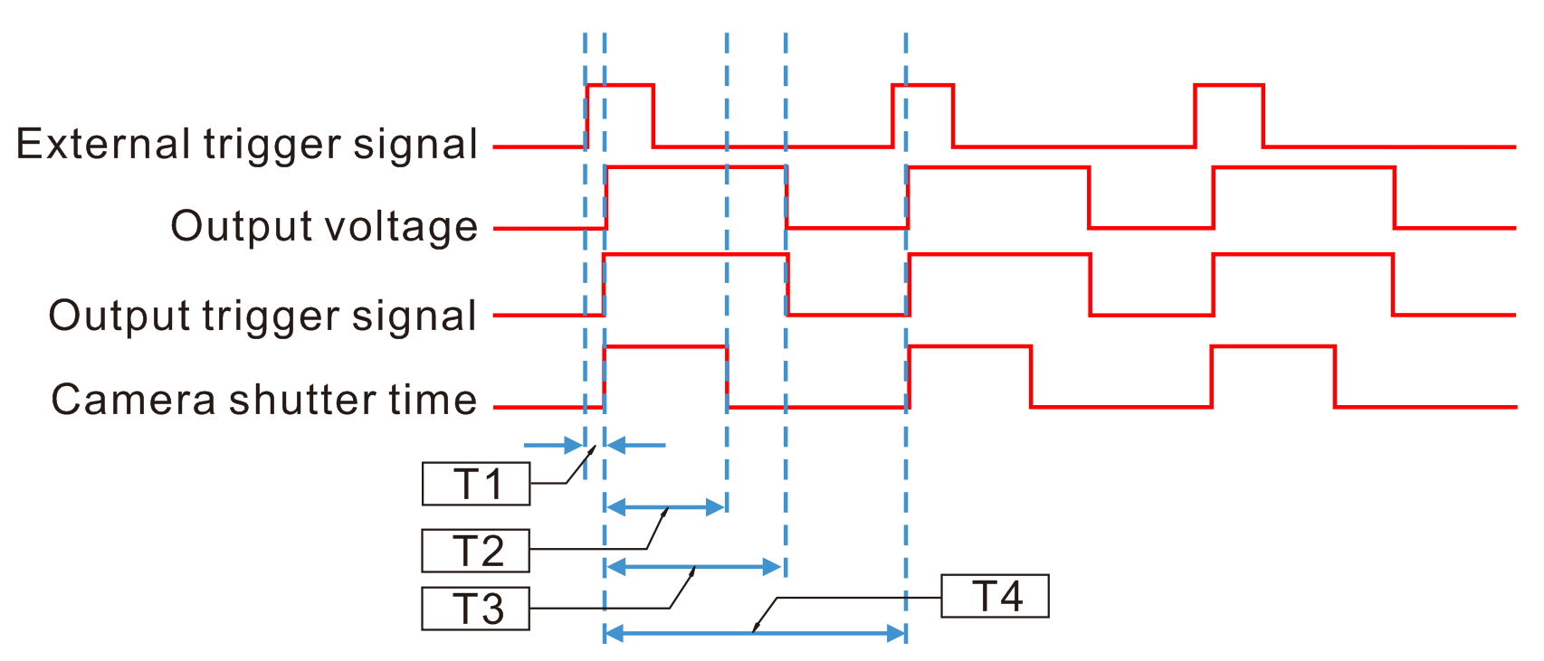
(1) The controller starts to work after it receives an external trigger signal. When a 48V voltage (its duration is T3, that’s the pulse width) is outputted from the light connector, the light is on. Because the voltage (48V) is twice higher than the rated voltage (24V), the intensity is also twice stronger than that in the normal condition.
(2)When a 48V voltage is outputted form the light connector, a 12V voltage signal is outputted from the camera trigger signal connector. The camera starts to take pictures after receiving the signal. When the camera’s shutter time(exposure time) is T2<T3, the light stays in high intensity status of 48V. The intensity of the picture is twice more than the normal one in this case.
(3)After the camera takes pictures, the light turns off when the output voltage duration reaches the set time T3 (pulse width). A working cycle is completed.
(4)T1 is the trigger delay of the controller, less than 20us. T4 is a working cycle of the controller which is 1.42ms.
(5)Because of T4=1.42ms, so the interval between the two triggers cannot be less than 1.42ms.
External Trigger Instruction
The strobing controller only has negative trigger.
Negative trigger: (the light is off without trigger access)
| Trigger signal situation | Suspended or high power trigger 5V-24V | Short circuit or low power trigger 0V-1.5V |
| External light response situation | Light flashes | Light is off |
The light will be on when the controller is connected with a 5V-24V trigger signal. The lighting time is determined according to the selected pulse width. The light is off when the trigger signal is 0V-1.5V or removed. The light returns to normal state.
Application Examples of the Strobing Controller
If the light keeps on (24V), the camera exposure time is 500us and the lens aperture is fixed, the image is dark. How to use the strobing controller to improve the brightness of the image without changing other conditions?
(1)Switching off the controller and connecting the light to the first channel connector (CH1).
(2)Connecting external trigger signal to trigger input connector(+1-) of the first channel(CH1).
(3)Connecting camera trigger to trigger signal output connector (the pin 3 and 5 of DB9 connector) of the controller and setting the camera to trigger camera mode in the computer at the same time.
(4)First, when you switch on the controller and press the button CH, the first number displayed on the digital showing screen is 1. Then, press the button + or -, the last number displayed is 0 (that is the normal working mode). Second, press the button CH again, the first number displayed is 1 and press the button + or -, the later three number displayed is 700 (more than 500 will do).
(5)The controller outputs a 48V to the light and a 12V signal to trigger the camera to take pictures when it receives an external trigger signal. The camera finishes taking pictures when the light is on and gets an image which brightness is twice stronger than the normal one.
Models of the Strobing Controller
Type | Model | Voltage | Power | No. of channels | Remarks |
Strobing Controller | KMN-STU4860-2 | 24V | 30Wx2 | 2 | With trigger function but without communication function |
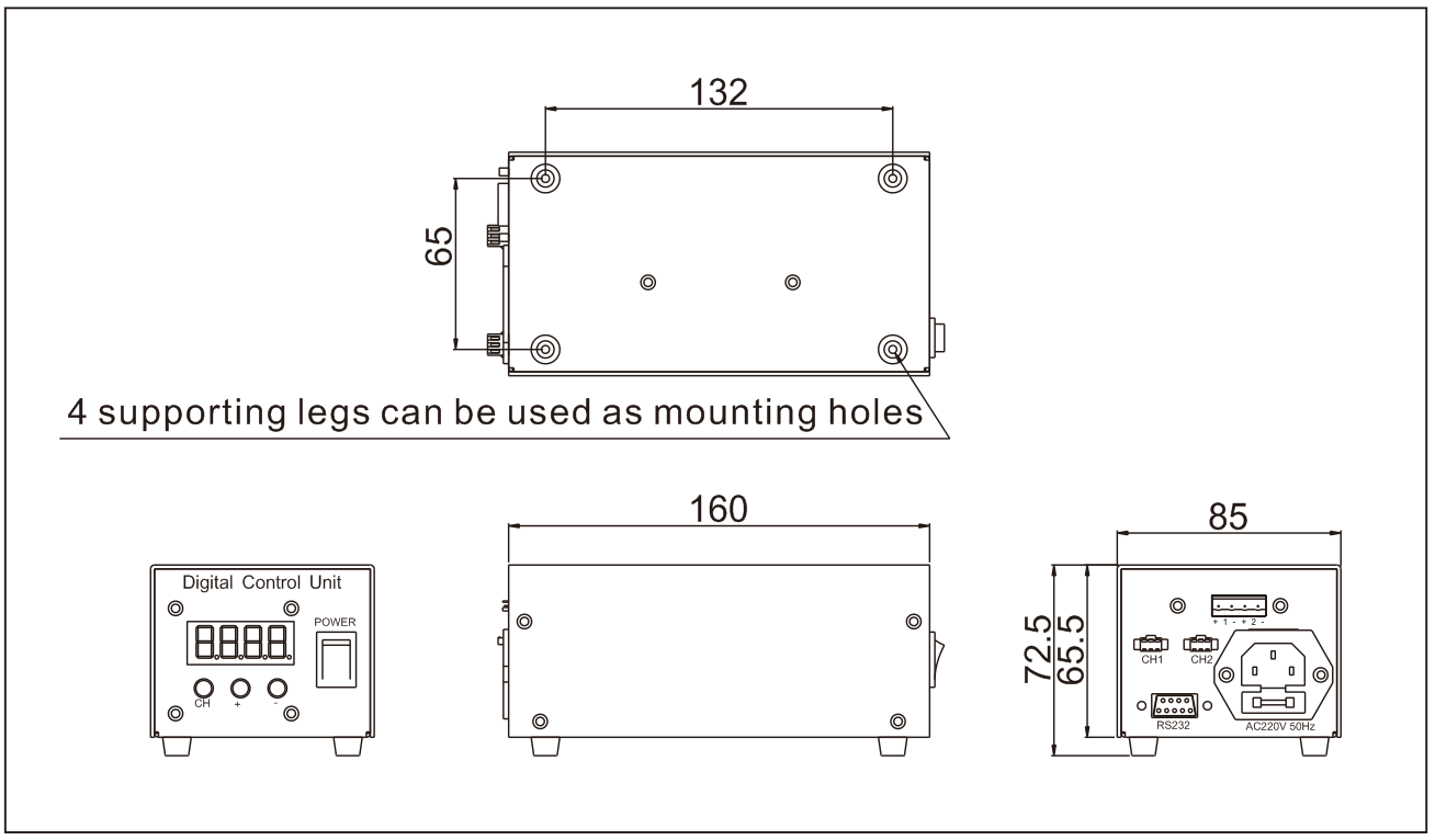
Dimensional Drawings