KMN-ACC
The constant-current controller sets light intensity to any of 256 levels ,which can be set by hand or PC; And the constant-current controller has the function of high/low level trigger,which can execute lights through external signals; This controller also has power-off memory function,which means previous parameter can be recorded after shutting down. This controller is property-stably and function-powerfully.
Features
1.High-integration and powerful-function
2.256-level adjustable intensity
3.Short-circuit protection function
4.Controlled by hand or PC
5.Power-off memory function
Parameter Description
| Model | KONMANN-ACC##-# | Remarks |
| Communication mode | RS232 | |
| Intensity control mode | Constant-current output, PWM control | Adjusting current by changing PWM duty cycle |
| Trigger delay time | <80us | Concerned with load |
| External trigger frequency | <1/T | Decided by strobe time. For instance=1ms, the maximum frequency can be reached 1K. |
| External trigger input voltage | High/low level trigger | Positive/negative trigger optionally |
| No.of channels | 1,2 channel(s) | |
| Intensity level | 256 level | |
| Drive mode | Constant-current system | |
| Input voltage | 100-240V |
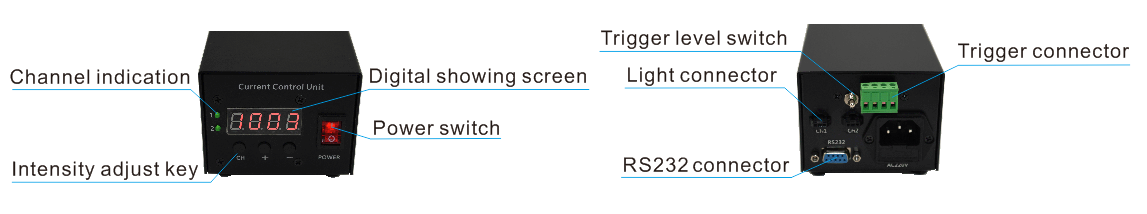
1.The function of intensity adjust keys
(1)From left, the first key (CH) is for“selection”, by which you can switch over displayed channels and set two channels.
(2)From left, the second key (+) is for “increasing level”, level parameter plus one, the intensity level plus one for every pushing.
(3)From left, the third key (-) is for “decreasing level”, level parameter minus one, the intensity level minus one for every pushing.
2.The content of digital showing screen
(1)From left, the first digit stands for channel displayed .When you push key “CH” the displayed number will be “1” or “2”. “1” and “2”stands for the channel that is setting up.
(2)When channel value is “1-2”,the latter 3 digits is parameter status bit. Displayed by decimal, the value will range from 000 to 255, which can be adjusted.
For example: When the digit is “1050”, the intensity level of the first channel is 50 levels.
3.Control unit wiring
(1) Connect the lights and control unit connector(Refer to operation panel instructions)
(2) If you want to precede external trigger, please connect external signal source with the connector of control unit trigger. “+”matches positive pole, “-”matches negative pole (Refer to operation panel instructions);
(3)Power source connect-in (AC 220V),pushing the red switch button“—”,“O” bulging with indicator light on, indicating power on.
4.Special circumstances instructions
(1) When channel value is“000”,the corresponding channel has no current output.
(2) When the value of parameter status bit of any one channel is between the number “001” and “255”, the corresponding channel output normally.
(3) After power source connect-in and control unit power-on, the digit tube will display the recorded parameter of last shut down. For example, if the control unit displays “1168”at last shut down, it will display “1168”when you restart.
External trigger instructions
The control unit has positive trigger and negative trigger, which can be set by the button switch(Refer to operation panel instructions).Customer can select trigger mode accordingly.
Positive trigger:(It will keep bright without trigger access.)
| Trigger signal output status | Vacancy or high level 5V-24V | Short circuit or low level 0V-1.5V |
| Connecting light source response status | Light up | Light out |
Negative trigger:(It will keep bright without trigger access.)
| Trigger signal output status | Vacancy or high level 5V-24V | Short circuit or low level 0V-1.5V |
| Connecting light source response status | Light out | Light up |
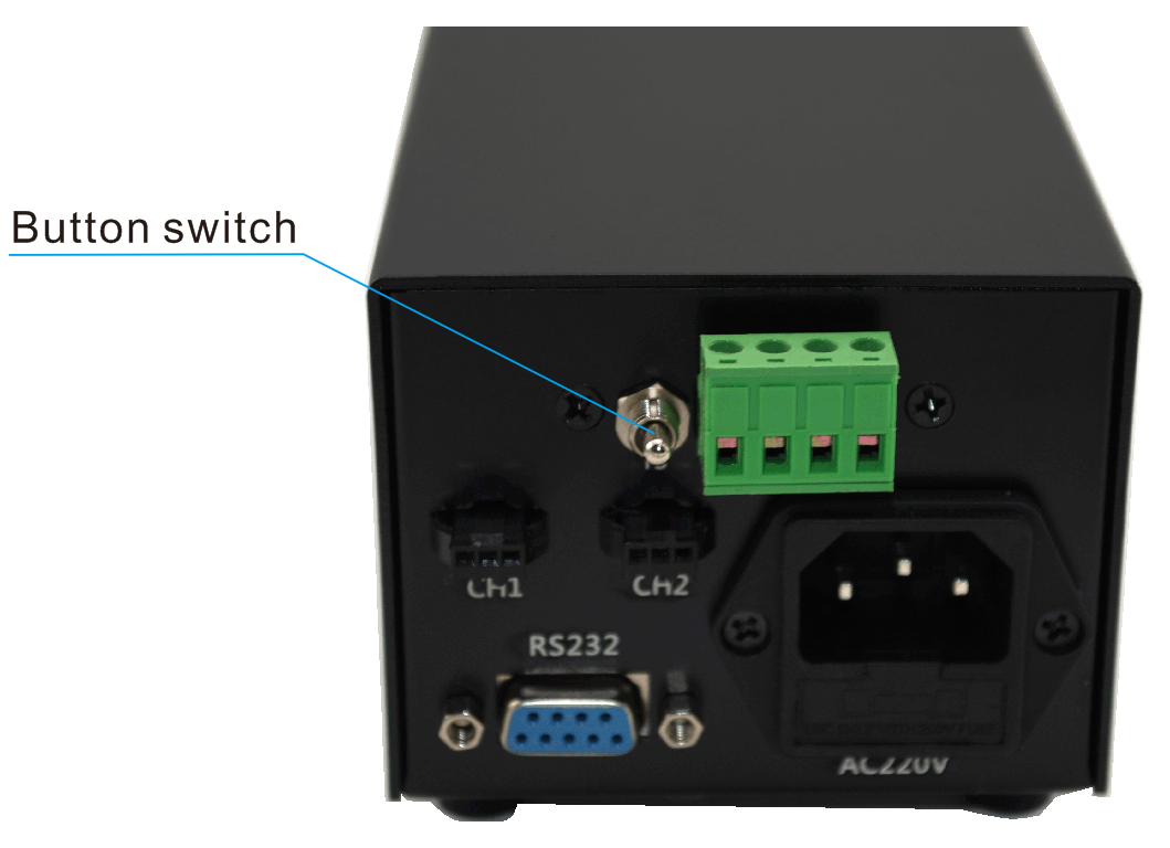
As it shows above,through button switch,you can set trigger mode of the control units.
(1) Button switch upward,stands for positive trigger.Output will be off when trigger connector short circuit or low level(0-1.5V)connect in.Output will be on when trigger signal canceled or the signal level turns to be(5-24V);
(2) Button switch downward,stands for negative trigger.Output will be on when trigger connector short circuit or low level(0-1.5V)connect in.Output will be off when trigger signal canceled or the signal level turns to be(5-24V).
Communication using instructions
Communication parameter
Baud rate | 9600 bps |
Data length | 8 bits |
Stop bit | 1 bit |
Odd-even check | None |
Communication data format(Refer to communication protocol for details)
| Word length | 1 byte | 1 byte | 1 byte | 3 byte | 2 byte |
| Functions | Tagged word | Command word | Channel word | Data word | XOR and check word |
Models of constant-current controller
Type | Model | Current | Power | Number of channels | Remarks |
Mini constant-current controller | KMN-ACC350-1M | 0.35A×1 | 1W×1 | 1 | Without communication function |
KMN-ACC350-2M | 0.35A×2 | 1W×2 | 2 | ||
KMN-ACC700-1M | 0.7A×1 | 2W×1 | 1 | ||
KMN-ACC700-2M | 0.7A×2 | <2W×2 | 2 | ||
Low power constant-current controller | KMN-ACC350-4 | 0.35A×4 | 1W×4 | 4 | Without displayed communication,with positive/negative trigger function |
KMN-ACC700-4 | 0.7A×4 | 2W×4 | 4 | ||
KMN-ACC350-2 | 0.35A×2 | 1W×2 | 2 | With trigger and communication function | |
KMN-ACC700-2 | 0.7A×2 | 2W×2 | 2 | ||
High power constant-current controller | KMN-ACC1500-2 | 1.5A×2 | 5W×2 | 2 |
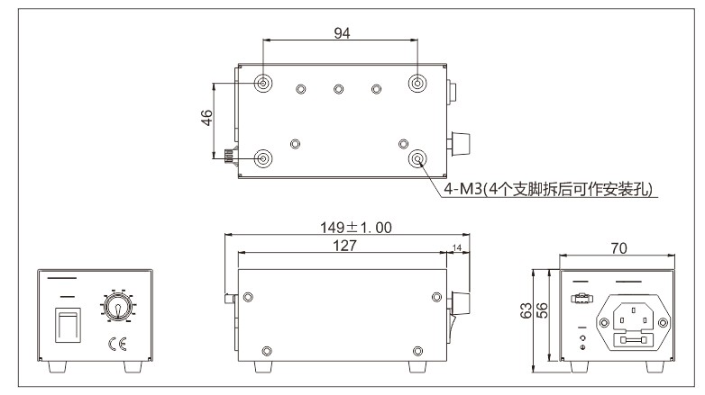
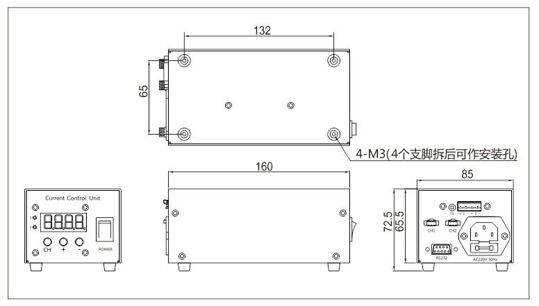
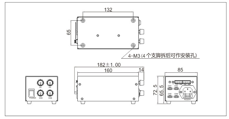
Dimensions
1.KMN-ACC350-1M/2M